Introduction
STM32mp15x Bootchain executes 4 sections until reaching Linux kernel :
1. ROM Code
2. FSBL (TF-A BL2)
3. OP-TEE
4. SSBL (U-boot)

If it doesn’t find it then it tries to find the fsbl at location LBA128 and location LBA640.
Once the binary image of FSBL (TF-A BL2) is found, ROM code moves it from SD Card into the internal SYSRAM.
One important property of this image is that: the image must contain a proprietary STM32 header. For STM32mp157x line, the size of this header is 256 bytes and it appears at the beginning of the binary. It’s header version is V1.0. ROM Code then jumps to the FSBL (TF-A BL2) and execution is controlled by FSBL from this point.
FSBL (TF-A BL2):
ROM Code is something which can not be changed and it is vendor specific. It is not in the users control. But TF-A BL2 is in the user control.
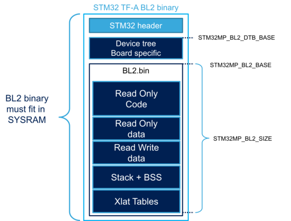

Image (left): Generic memory map of TF-A BL2 (Not specific to STM32mp157f) Image source: section 4 of https://wiki.st.com/stm32mpu/wiki/TF-A_BL2_overview Image (right): memory map. Image source: section 2.5.2 of reference manual of stm32mp15x
Where does ROM code jumps after loading the TF-A BL2 firmware ?
According to the memory layout of the product, the SYSRAM starts at the location 0x2FFC0000. But the BL2.bin doesn’t start at the same address because first header and device tree are placed at the beginning.
Finding the starting address of BL2.bin:
To find out the address, below #defines are found from the source
#define STM32MP_BINARY_BASE (STM32MP_SEC_SYSRAM_BASE + STM32MP_PARAM_LOAD_SIZE + STM32MP_HEADER_SIZE)

#define STM32MP_SEC_SYSRAM_BASE STM32MP_SYSRAM_BASE

#define STM32MP_SYSRAM_BASE U(0x2FFC0000)
#define STM32MP_PARAM_LOAD_SIZE U(0x00002400) /* 9 KB for param */
#define STM32MP_HEADER_SIZE U(0x00000100) /* 256 Octets reserved for header */

After doing the addition:
STM32MP_BINARY_BASE = 0x2FFC2500
Finding the starting address of entry point:
Above, binary base is resolved by using #defines manually but its not practical to resolve everything so readers can sort it out rest of the things by reading below linker labels and linker script: __BL2_IMAGE_START__ = 0x2ffe9000
So, after the header verification is done, ROM code jumps to the address 0x2ffe9000. It is the address of function “bl2_entrypoint”
OUTPUT_FORMAT("elf32-littlearm")
OUTPUT_ARCH(arm)
ENTRY(__BL2_IMAGE_START__)
MEMORY {
HEADER (rw) : ORIGIN = 0x00000000, LENGTH = (0x3000)
RAM (rwx) : ORIGIN = ((0x2FFC0000) + (0x00002400) + (0x00000100)), LENGTH = (((0x00040000) - ((1) << (12))) - ((0x00002400) + (0x00000100)))
}
SECTIONS
{
.header : {
__HEADER_START__ = .;
KEEP(*(.header))
. = ALIGN(4);
__HEADER_END__ = .;
} >HEADER
. = ((0x2FFC0000) + (0x00002400) + (0x00000100));
.data . : {
. = ALIGN(((1) << (12)));
__DATA_START__ = .;
*(.data*)
. = ( (((0x2FFC0000) + ((0x00040000) - ((1) << (12))) - (0x00016000)) - (0x00007000)) - ((0x2FFC0000) + (0x00002400) + (0x00000100)) );
__DTB_IMAGE_START__ = .;
*(.dtb_image*)
__DTB_IMAGE_END__ = .;
. = ( ((0x2FFC0000) + ((0x00040000) - ((1) << (12))) - (0x00016000)) - ((0x2FFC0000) + (0x00002400) + (0x00000100)) );
__BL2_IMAGE_START__ = .;
*(.bl2_image*)
__BL2_IMAGE_END__ = .;
__DATA_END__ = .;
} >RAM
__TF_END__ = .;
}
Name Origin Length Attributes
HEADER 0x00000000 0x00003000 rw
RAM 0x2ffc2500 0x0003cb00 xrw
*default* 0x00000000 0xffffffff
Linker script and memory map
.header 0x00000000 0x0
0x00000000 __HEADER_START__ = .*(.header)
0x00000000 . = ALIGN (0x4)
0x00000000 __HEADER_END__ = .
0x2ffc2500 . = 0x2ffc2500
.data 0x2ffc2500 0x380bd
0x2ffc3000 . = ALIGN (0x1000)
*fill* 0x2ffc2500 0xb00
0x2ffc3000 __DATA_START__ = .
*(.data*)
.data 0x2ffc3000 0x0 stm32mp1-stm32mp157f-dk2.o
0x0001fb00 . = 0x1fb00
*fill* 0x2ffc3000 0x1f000
0x2ffe2000 __DTB_IMAGE_START__ = .
*(.dtb_image*)
.dtb_image 0x2ffe2000 0x3d58 stm32mp1-stm32mp157f-dk2.o
0x2ffe5d58 __DTB_IMAGE_END__ = .
0x00026b00 . = 0x26b00
*fill* 0x2ffe5d58 0x32a8
0x2ffe9000 __BL2_IMAGE_START__ = .
*(.bl2_image*)
.bl2_image 0x2ffe9000 0x115bd stm32mp1-stm32mp157f-dk2.o
0x2fffa5bd __BL2_IMAGE_END__ = .
0x2fffa5bd __DATA_END__ = .
0x2fffa5bd __TF_END__ = .
LOAD stm32mp1-stm32mp157f-dk2.o
OUTPUT(tf-a-stm32mp157f-dk2.elf elf32-littlearm)
LOAD linker stubs
.bss 0x2fffa5bd 0x0
.bss 0x2fffa5bd 0x0 stm32mp1-stm32mp157f-dk2.o
.ARM.attributes
0x00000000 0x27
.ARM.attributes
0x00000000 0x27 stm32mp1-stm32mp157f-dk2.o
4. Build and Configure TF-A BL2
By using default configuration OP-TEE would go into DDR but according to above diagram it needs to be in SYSRAM (256 KB) thats why
STM32MP1_OPTEE_IN_SYSRAM needs to be set to 1
make ARM_ARCH_MAJOR=7 ARCH=aarch32 PLAT=stm32mp1 \
DTB_FILE_NAME=stm32mp157f-dk2.dtb \
AARCH32_SP=optee \
STM32MP1_OPTEE_IN_SYSRAM=1 \
BL32=../optee_os/out/arm-plat-stm32mp1/core/tee-header_v2.bin \
BL32_EXTRA1=../optee_os/out/arm-plat-stm32mp1/core/tee-pager_v2.bin \
BL32_EXTRA2=../optee_os/out/arm-plat-stm32mp1/core/tee-pageable_v2.bin \
BL33=../u-boot/u-boot-nodtb.bin \
BL33_CFG=../u-boot/u-boot.dtb \
STM32MP_SDMMC=1 \
fip all
After running the above make command, file tf-a-stm32mp157f-dk2.stm32 would be generated in folder arm-trusted-firmware/build/stm32mp1/release. file “tf-a-stm32mp157f-dk2.stm32” will be later flashed in SD card.